Creative software developers at Sveasoft have extended the LINKSYS WRT54G router's Operating System (Linux based) to include the capability of running /usr/sbin/rflow, a Cisco NetFlow data generator implementation. They have integrated ntop's PF_RING-enabled kernel patch. This patch provides a means for faster packet capture (i.e. minimize packet capture loss) and also captures packets more efficiently thus preserving CPU cycles. The combination of a LINKSYS WRT54G router running rflow (a NetFlow generator) and a NST probe running ntop (a NetFlow collector) provides a low cost solution for remote network traffic usage and activity (NetFlow monitoring).
We will use the example network diagrammed in Figure 8.1, “Ntop, NetFlow, WRT54GS LINKSYS Router - network flow monitoring” for our NetFlow demonstration. The objective of this demonstration is to use a NetFlow probe to monitor all network traffic entering and leaving the internet side of the Firewall (FW2 Interface: vlan1) at Satellite Office Site: B remotely from a network monitoring system at the Corporate Headquarter Site: A. The NetFlow probe in this case is a LINKSYS WRT54GS router. The NST probe shown will run ntop with a NetFlow plugin configured to collect NetFlow data from the WRT54GS NetFlow probe.
Some complexity was added in this demonstration by enabling secure remote access to the ntop visual web user interface. We will use a Secure Shell (SSH) session and tunnel HTTPS packets from the NST probe (ntop collector) to the Windows XP desktop (network monitoring station). Both Network (24.29.60.245 <=> 192.168.2.51) and Port Address Translation (SSH:22222 <=> SSH:22) (NAT/PAT) will also be used.
Note
In this demonstration it may seem overkill to use a secure tunnel and transport an already encrypted HTTPS (SSL) data stream within the SSH session. One may need to do this if the local security policy dictates that only a secure shell port (SSH:22222) may be allowed open on the Firewall (FW2).
One will need to be aware of the network traffic generated between the NST probe running ntop and the Windows XP monitoring station given that this traffic flows through the Firewall FW2 vlan1 interface. Make sure that your measurements are not altered by this traffic.
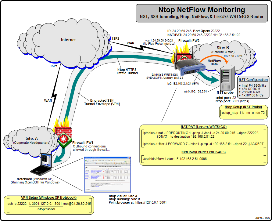
The NAT/PAT configuration on the WRT54GS using iptables is shown. The exact insertion of the FORWARDING and PREROUTING chain rules in the filter and nat table respectively will depend on the current iptables configuration.
The Windows XP monitoring station is using OpenSSH for Windows. The VPN setup for tunnelling the ntop HTTPS traffic is display on Figure 8.1, “Ntop, NetFlow, WRT54GS LINKSYS Router - network flow monitoring”. TCP port: 3001 will be tunneled through the SSH encypted envelope and be available on the Windows XP at URL: https://127.0.0.1:3001.
The startup dialog for running the /usr/sbin/rflow NetFlow application on the WRT54GS router is shown below:
[root@wrt54gs tmp]#/usr/sbin/rflow -i vlan1 -F 192.168.2.51:9996Opening vlan1... [LCap] Open RING [fd=3] RING (vlan1): tot_slots=8004/slot_len=131/insertIdx=0/remove_idx=0/dropped=0 apply filter... Initialized as 1 Configured NetFlow destination at 192.168.2.51:9996 NetFlow destination thread started. Thread 2051 processing vlan1 started.
Note
We assume that one has access to the WRT54GS command prompt. This can be done through a SSH session from the NST probe to the WRT54GS router.
Useful NetFlow text data is available from the /usr/sbin/rflow application by using the "Ctrl-c" key sequence:
  44 flows, 0 flow alloc failures
  Active flows timeout in 30 minutes
  Inactive flows timeout in 15 seconds

SrcIf         SrcIPaddress    DstIf         DstIPaddress    Pr SrcP DstP  Pkts
vlan1         216.109.118.67  <?>           24.29.60.245    06 0050 9489     4
vlan1         24.29.60.245    <?>           216.109.118.67  06 9489 0050     6
vlan1         216.109.117.106 <?>           24.29.60.245    06 0050 9488    25
vlan1         24.29.60.245    <?>           216.109.117.106 06 9488 0050    26
vlan1         216.109.118.67  <?>           24.29.60.245    06 0050 9487    25
vlan1         24.29.60.245    <?>           216.109.118.67  06 9487 0050    26
vlan1         216.109.118.78  <?>           24.29.60.245    06 0050 9486    25
vlan1         24.29.60.245    <?>           216.109.118.78  06 9486 0050    26
vlan1         216.109.118.73  <?>           24.29.60.245    06 0050 9485    25
vlan1         24.29.60.245    <?>           216.109.118.73  06 9485 0050    26
vlan1         216.109.118.77  <?>           24.29.60.245    06 0050 9484    25
vlan1         24.29.60.245    <?>           216.109.118.77  06 9484 0050    26
vlan1         216.109.117.106 <?>           24.29.60.245    06 0050 9483    25
vlan1         24.29.60.245    <?>           216.109.117.106 06 9483 0050    26
vlan1         216.109.118.74  <?>           24.29.60.245    06 0050 9482    25
vlan1         24.29.60.245    <?>           216.109.118.74  06 9482 0050    26
vlan1         216.109.118.66  <?>           24.29.60.245    06 0050 9481    25
vlan1         24.29.60.245    <?>           216.109.118.66  06 9481 0050    26
vlan1         216.109.118.77  <?>           24.29.60.245    06 0050 9480    25
vlan1         24.29.60.245    <?>           216.109.118.77  06 9480 0050    26
vlan1         216.109.118.66  <?>           24.29.60.245    06 0050 947f    25
vlan1         24.29.60.245    <?>           216.109.118.66  06 947f 0050    26
vlan1         216.109.118.67  <?>           24.29.60.245    06 0050 947e    25
vlan1         24.29.60.245    <?>           216.109.118.67  06 947e 0050    26
vlan1         216.109.118.67  <?>           24.29.60.245    06 0050 947d    25
vlan1         24.29.60.245    <?>           216.109.118.67  06 947d 0050    26
vlan1         216.109.118.77  <?>           24.29.60.245    06 0050 947c    25
vlan1         24.29.60.245    <?>           216.109.118.77  06 947c 0050    26
vlan1         216.109.118.78  <?>           24.29.60.245    06 0050 947b    25
vlan1         24.29.60.245    <?>           216.109.118.78  06 947b 0050    26
vlan1         216.109.118.77  <?>           24.29.60.245    06 0050 947a    25
vlan1         24.29.60.245    <?>           216.109.118.77  06 947a 0050    26
vlan1         216.109.117.106 <?>           24.29.60.245    06 0050 9479    25
vlan1         24.29.60.245    <?>           216.109.117.106 06 9479 0050    26
vlan1         216.109.118.66  <?>           24.29.60.245    06 0050 9478    25
vlan1         24.29.60.245    <?>           216.109.118.66  06 9478 0050    26
vlan1         216.109.118.77  <?>           24.29.60.245    06 0050 9477    25
vlan1         24.29.60.245    <?>           216.109.118.77  06 9477 0050    26
vlan1         10.119.0.1      <?>           255.255.255.255 11 0043 0044     2
vlan1         24.29.60.245    <?>           24.194.134.127  06 56ce 0883   635
vlan1         24.92.32.22     <?>           24.29.60.245    11 0035 82f1    20
vlan1         24.29.60.245    <?>           24.92.32.22     11 82f1 0035    20
vlan1         24.194.134.127  <?>           24.29.60.245    06 0883 56ce   683
vlan1         0.0.0.0         <?>           255.255.255.255 11 0044 0043    93
Once the ntop application is started on the NST probe (in this example we used: /usr/local/bin/setup_ntop -i lo -no c -rds 72) the NetFlow plugin needs to be configured. The following is configured for this ntop instance:
The direct interface is the loopback interface: lo option: ("-i lo"). We are only interested in the NetFlow plugin traffic.
Enable the ntop "sticky-hosts" option: ("-c") so that all hosts detected by ntop over time will not be purged.
A 72 MByte RAM Disk is created at mount point: /mnt/ram4 option: ("-rds 72").
The ntop screen capture shown in Figure 8.2, “Ntop NetFlow plugin configuration” displays the ntop configuration for the NetFlow plugin using our example network.

For our NetFlow probe we chose to use UDP port: 9996.
Note
Do not forget to make the NetFlow plugin Active after configuring the NetFlow parameters. Also remember to switch the reporting NIC to the configued NetFlow-device.
The following ntop screen capture shows a portion of the "Global Traffic Statistics" for the NetFlow-device:

The ntop screen capture below shows actual NetFlow traffic captured from the WRT54GS NetFlow probe:

Lastly a screen capture is shown displaying an actual NetFlow UDP packet in detail mode. This was done by using the wireshark protocol analyzer network application on the NST.

Note
This particular NetFlow UDP packet includes 4 flows. The one shown in expanded detail is a TCP HTTP packet (port: 80) between www.dnc.yahoo.com and the NST probe. The NST probe made a wget request to the yahoo web site for generation of this flow. Notice the NST probe was masqueraded (NATed) by the vlan1 interface: 192.168.2.51 <=> alb-24-29-60-245.nycap.rr.com (24.29.60.245).
This section lists the WRT54GS iptables table and chain configurations for the demonstration network shown in Figure 8.1, “Ntop, NetFlow, WRT54GS LINKSYS Router - network flow monitoring”.
The iptables listing for table filter chain INPUT on the WRT54GS router is shown below:
[root@wrt54gs tmp]#/usr/sbin/iptables -t filter -L INPUT -v -n --line-numbersChain INPUT (policy ACCEPT 0 packets, 0 bytes) num pkts bytes target prot opt in out source destination 1 2952 230K ACCEPT all -- * * 0.0.0.0/0 0.0.0.0/0 state RELATED,ESTABLISHED 2 0 0 DROP udp -- vlan1 * 0.0.0.0/0 0.0.0.0/0 udp dpt:520 3 0 0 DROP udp -- br0 * 0.0.0.0/0 0.0.0.0/0 udp dpt:520 4 0 0 ACCEPT udp -- * * 0.0.0.0/0 0.0.0.0/0 udp dpt:520 5 0 0 ACCEPT tcp -- * * 0.0.0.0/0 192.168.2.1 tcp dpt:443 6 41 2341 DROP icmp -- * * 0.0.0.0/0 0.0.0.0/0 7 2 64 ACCEPT igmp -- * * 0.0.0.0/0 0.0.0.0/0 8 7 496 ACCEPT all -- lo * 0.0.0.0/0 0.0.0.0/0 state NEW 9 2262 779K logaccept all -- br0 * 0.0.0.0/0 0.0.0.0/0 state NEW 10 46457 25M DROP all -- * * 0.0.0.0/0 0.0.0.0/0[root@wrt54gs tmp]#
The iptables listing for table filter chain FORWARD on the WRT54GS router is shown below:
[root@wrt54gs tmp]#/usr/sbin/iptables -t filter -L FORWARD -v -n --line-numbersChain FORWARD (policy ACCEPT 0 packets, 0 bytes) num pkts bytes target prot opt in out source destination 1 0 0 ACCEPT all -- br0 br0 0.0.0.0/0 0.0.0.0/0 2 0 0 logdrop all -- * * 0.0.0.0/0 0.0.0.0/0 state INVALID 3 0 0 ACCEPT udp -- vlan1 * 0.0.0.0/0 224.0.0.0/4 udp 4 125K 48M TRIGGER all -- vlan1 br0 0.0.0.0/0 0.0.0.0/0 TRIGGER type:in match:0 relate:0 5 129K 33M trigger_out all -- br0 * 0.0.0.0/0 0.0.0.0/0 6 129K 33M lan2wan all -- br0 * 0.0.0.0/0 0.0.0.0/0 7 98546 13M ACCEPT tcp -- vlan1 * 0.0.0.0/0 192.168.2.51 tcp dpt:22 8 155K 67M ACCEPT all -- * * 0.0.0.0/0 0.0.0.0/0 state RELATED,ESTABLISHED 9 1434 89351 ACCEPT all -- br0 * 0.0.0.0/0 0.0.0.0/0 state NEW 10 0 0 DROP all -- * * 0.0.0.0/0 0.0.0.0/0[root@wrt54gs tmp]#
The iptables listing for table nat chain PREROUTING on the WRT54GS router is shown below:
[root@wrt54gs tmp]#/usr/sbin/iptables -t nat -L PREROUTING -v -n --line-numbersChain PREROUTING (policy ACCEPT 47875 packets, 26M bytes) num pkts bytes target prot opt in out source destination 1 4 192 DNAT tcp -- vlan1 * 0.0.0.0/0 24.29.60.245 tcp dpt:22222 to:192.168.2.51:22 2 0 0 DNAT tcp -- * * 0.0.0.0/0 24.29.60.245 tcp dpt:8080 to:192.168.2.1:443 3 40 2229 DNAT icmp -- * * 0.0.0.0/0 24.29.60.245 to:192.168.2.1[root@wrt54gs tmp]#
The iptables listing for table nat chain POSTROUTING on the WRT54GS router is shown below:
[root@wrt54gs tmp]#/usr/sbin/iptables -t nat -L POSTROUTING -v -n --line-numbersChain POSTROUTING (policy ACCEPT 216 packets, 63447 bytes) num pkts bytes target prot opt in out source destination 1 1498 96873 MASQUERADE all -- * vlan1 0.0.0.0/0 0.0.0.0/0 2 676 69904 MASQUERADE all -- * br0 192.168.2.0/24 192.168.2.0/24[root@wrt54gs tmp]#